TDM Pulse Code Modulation Receiver
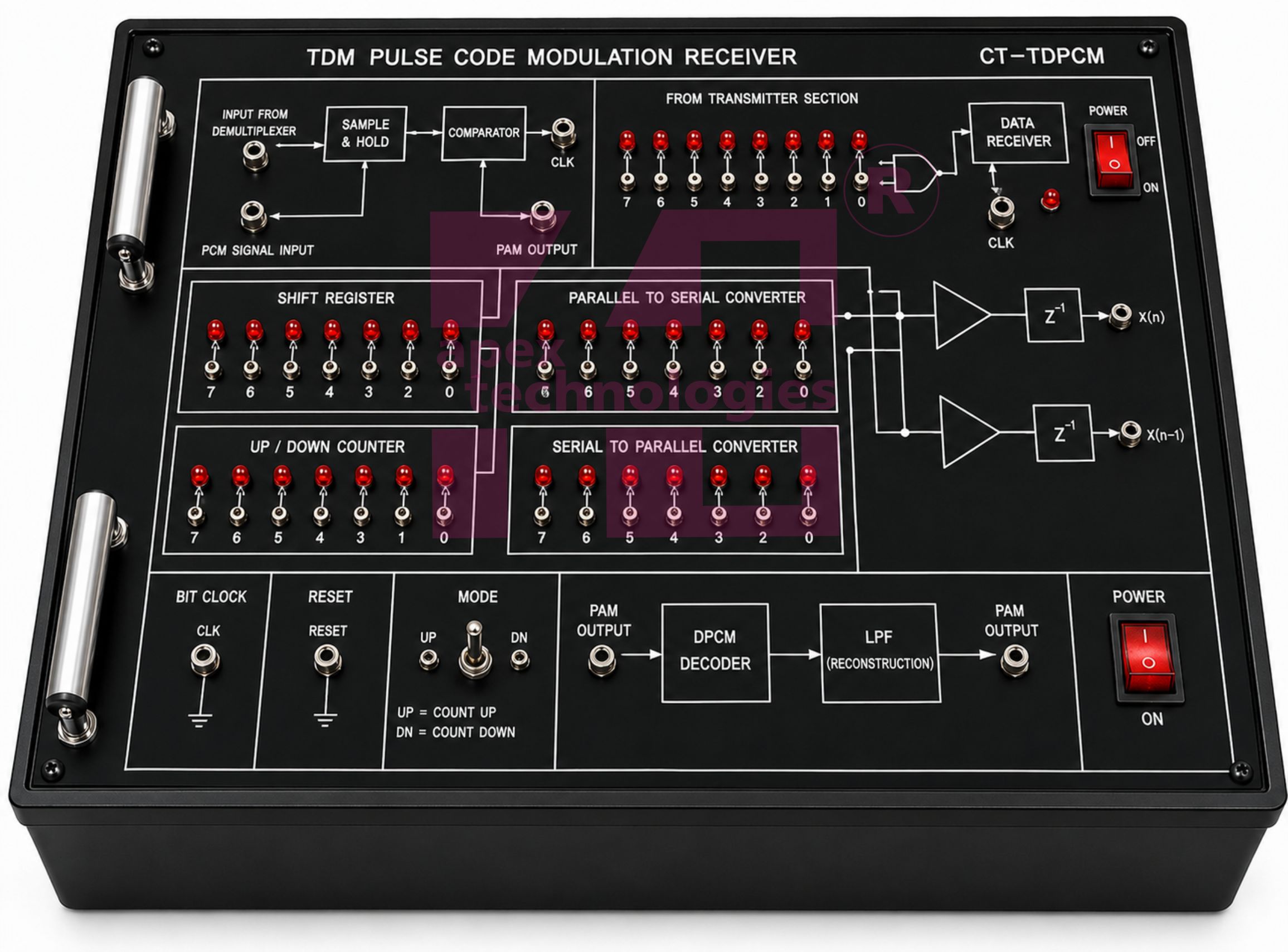
TDM Pulse Code Modulation Receiver
TDM Pulse Code Modulation Receiver demonstrates Pulse Code Demodulation Technique which is the most widely used digital demodulation system. Since analog modulation system is most prone to noise present in the channel and receiver, the digital modulation system is used because it is less sensitive to noise. The basis of digital modulation systems lies on pulse code modulation i.e. a particular characteristic of the pulse is varied in accordance with the information signal. In PCM system the amplitude of the sampled waveform at definite time intervals is represented as a binary code.
Technical Specifications
Crystal Frequency : 6.4/8 MHz
Analog Input channel : 4
Multiplexing : Time Division Multiplexing
Modulation : Pulse Amplitude Modulation
On – Board Analog Signal : 250 Hz, 500 Hz, 1 KHz, 2KHz 500 Hz, 1 KHz, 2KHz, 4KHz (optional)
Sampling Rate : 16 KHz / Channel
Sampling Pulse : With Duty Cycle variable from 0 – 90% in decade steps Clock Resistance at Receiver : Using PLL
Low Pass Filter cut – off Freq. : 3.4 KHz
Fault Switches : 4 nos. through 4 way DIP switch for troubleshooting at different blocks
Test Points : More than 50
Interconnections : 2/4 mm socket
Cabinet : Enclosed in ABS plastic cabinet with detachable cover
Power : 220V AC ±10%, 50/60Hz mains operated
Accessories : Set of Patch Cords, User’s manual